


PXIe720 FPGA board which is, a powerful, flexible, and expandable PXIe module, fully compatible with PXI™-5 and ANSI-Vita-57.4 FMC+ carrier standards. PXIe is the platform of choice for the test &measurements, instrumentation applications as well as the defense market. The presence of an FMC+ site gives the user the ability to add different functionalities through the many available FMC+ boards from Sundance DSP or other vendors. The host interface is via a x4 Gen3 PCIe Link. The PCIe interface is implemented through firmware built using the latest Xilinx tools. The Xilinx-supported implementation avoids any licensing costs. The onboard FLASH can be used to store up to three-bit streams for configuring the FPGA through the driver from the host. A JTAG interface is also available for reconfiguring the FPGA from a host during development and debugging via logic analyzers.
The PXIe720 FMC+ carrier card, which is the replacement for our popular PXIe700 FPGA peripheral board, has several updates and improvements over the PXIe700 while keeping key features like support for White Rabbit communication protocol:
Board is based on AMD / Xilinx XCKU060-2FFVA1517 but can also use XCKU085 and XCKU115;
SFP+ cage to provide 10Gb Ethernet;
HPC FMC+ connector with 23 DP 16.3 gigabit serial links, 34 LA, 24 HA, and 22 HB lanes;
8GB 64-bit wide DDR4 memory;
512MB of QSPI flash with multi-boot capabilities;
Clock resources to support White Rabbit extreme-precision time protocol via SFP+ fiber.
Features:
- PXIe form factor with 8 lanes of PCIe Gen 3 EP interface to host;
- PXI control signals for instrumentation support;
- Base FPGA is XCKU060-2FFVA1517E, also can support XCKU085 and XCKU115 version as build option;
- SFP+ cage to provide 10Gb Ethernet;
- HPC FMC+ connector with 23 FMC_DP 16.3 Gbps serial links, 34 LA, 24 HA and 22 HB lanes;
- Supported VADJ – 1.0 – 1.8V;
- Two channels of DDR4 SDRAM memory, each 4GB deep and 32-bit wide, base chip is MT40A1G16TB-062E;
- 128MB of QSPI flash with multi-boot capability;
- Core power up to 50Amps;
- Four User LEDs, two of them visible from front panel, power good LEDs, not visible from front panel;
- Clock resources to support White Rabbit extreme-precision time protocol via SFP+ fiber.
- MMCX internal connectors for:
- 2 Transceivers from 229 Bank – differential input/output;
- Reference clock for 229 Bank – differential input;
- Reference clock for Bank 24 – input SE 1.8V LVCMOS.
- 2 front panel RGB LED
|
 |
 |
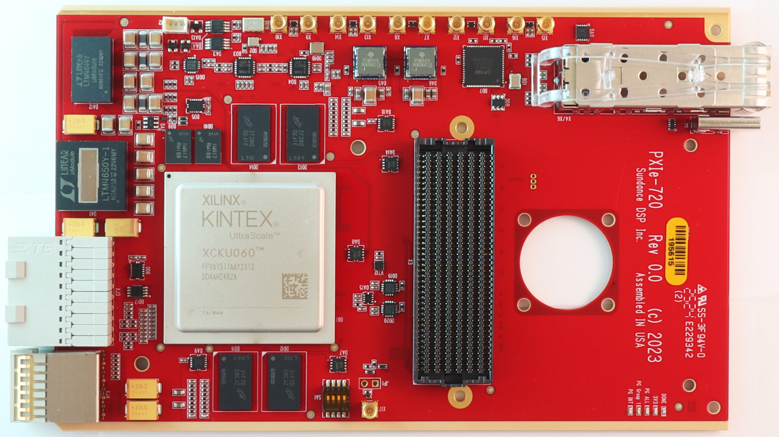 |
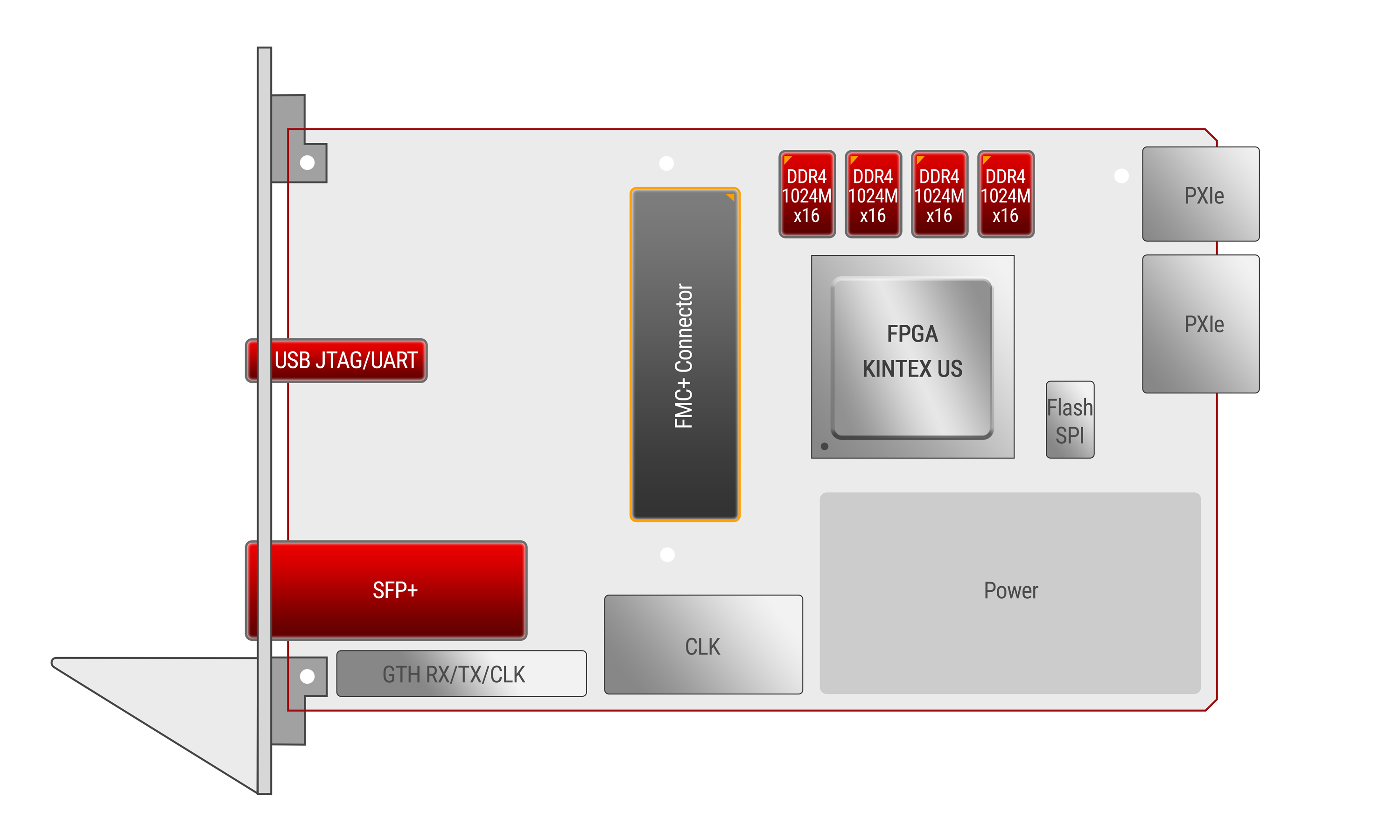
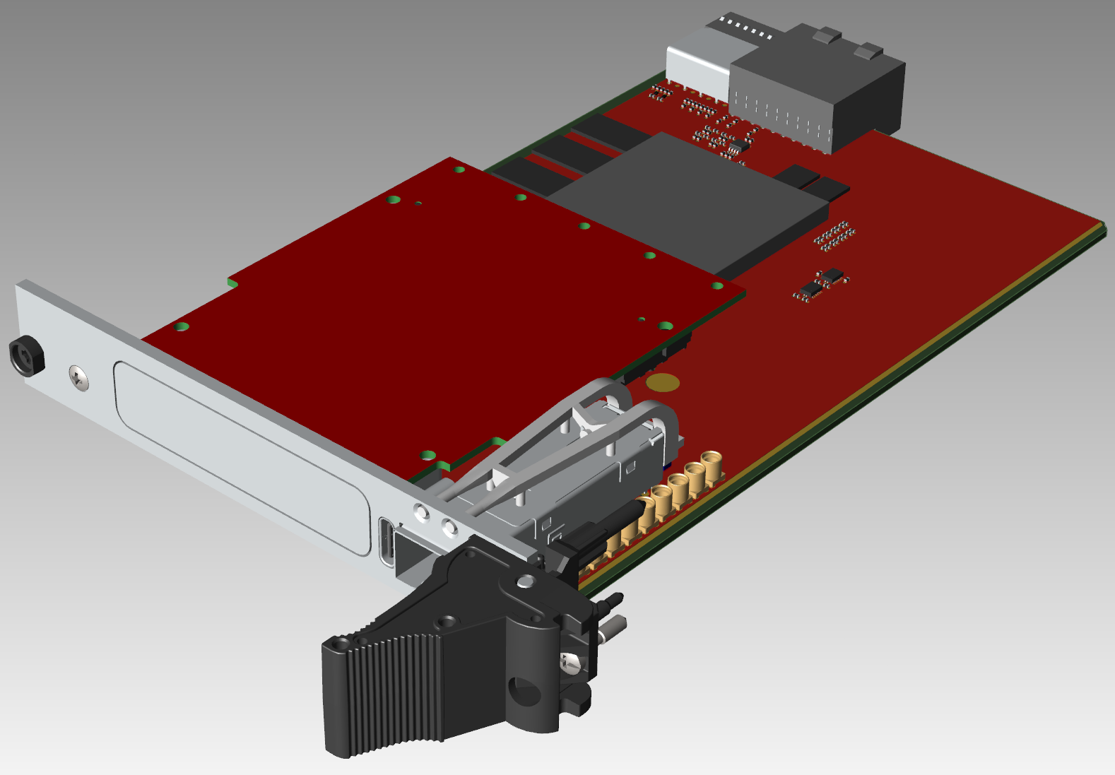
| PXIe720 Front panel | Placement Diagram | PXIe720&FMC+ | Front View |
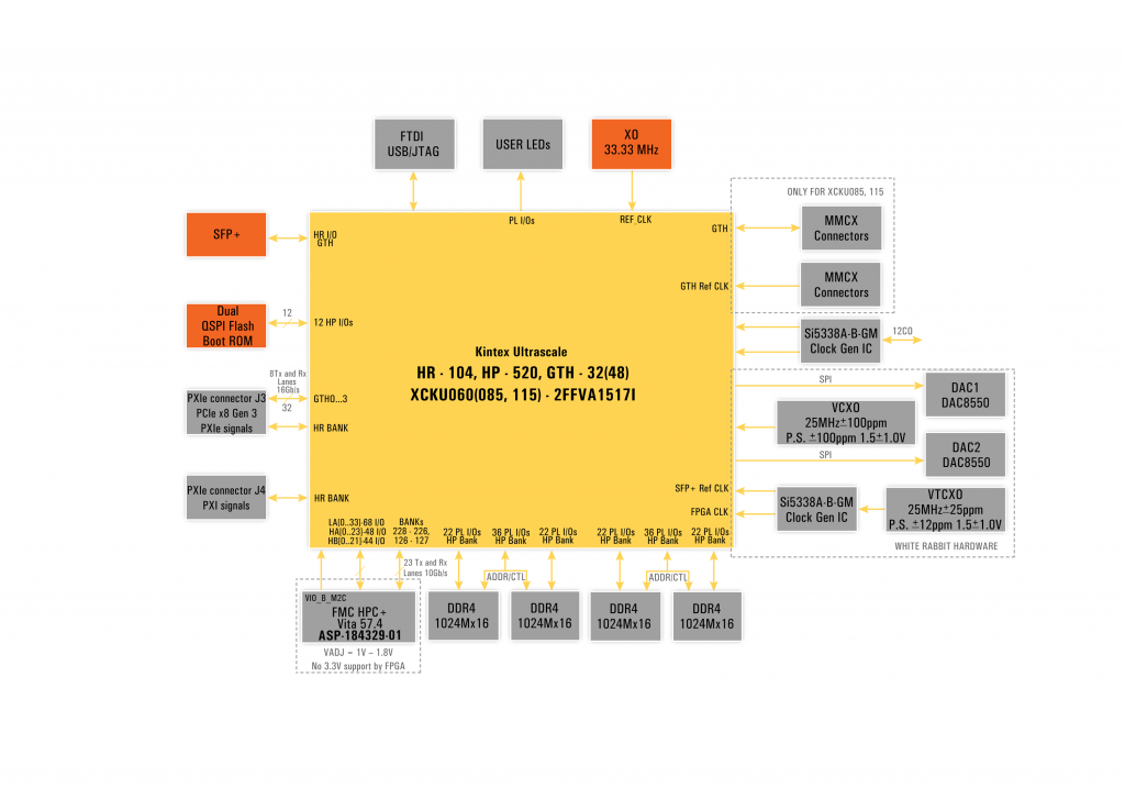
Block Diagram
A full BSP including is included. Host-side Linux and Windows PCIe DMA drivers are also supplied.
PXIe720-t-c where as:
t : can be I for industrial and if E or blank then it is extended temp.
c : if blank then it indicates the default FPGA part XCKU060-2FFVA1517 or it can be XCKU085-2FFVA1517 or XCKU115-2FFVA1517
Example parts:
PXIe720-I-XCKU115-2FFVA1517 industrial grade PXIe720 with part XCKU115-2FFVA1517
PXIe720-XCKU085-2FFVA1517 extended temperature grade PXIe720 with part XCKU085-2FFVA1517