
Two standards, one mezzanine ecosystem
The FPGA Mezzanine Card family gives hardware engineers a way to separate the FPGA carrier from the I/O front end. Buy one carrier, swap the mezzanine, and the same processing platform becomes a data acquisition system, an RF transceiver, a camera interface, or a network tap.
There are two generations in play. FMC is defined by VITA 57.1 and has been the workhorse of FPGA prototyping for well over a decade. It comes in two connector variants. LPC uses a 160-pin connector and normally exposes one multi-gigabit transceiver pair (DP0) plus its associated reference clock, though some implementations route a little more. HPC uses a 400-pin connector carrying 160 single-ended user I/O signals and up to ten transceiver pairs, DP0 through DP9. The user I/O splits into three banks: LA with 34 differential pairs, HA with 24, and HB with 22.
FMC+ is defined by VITA 57.4 and was introduced to keep pace with converters and optics that outran the older connector. Its HSPC connector carries 560 pins in a 14 × 40 arrangement and supports up to 24 transceiver pairs. The optional HSPCe variant adds a secondary connector that takes the total as high as 32. The parallel I/O banks and the management signalling were deliberately kept familiar, which is what makes mixing generations possible at all.
That familiarity is the point of this article. Most labs own a mixture: an older carrier that still works perfectly, a newer mezzanine bought for a new project, and a deadline that does not allow for a board respin. Knowing which combinations plug together directly, which need an interposer, and what you give up in each case is the difference between a week of integration and a month of it.
Direction one: an FMC mezzanine on an FMC+ carrier
This is the easy direction, and it works because VITA 57.4 was written as a superset of VITA 57.1. The HSPC connector on an FMC+ carrier is arranged so that a standard FMC HPC or LPC module mates with the corresponding subset of its rows, with the keying and polarisation ensuring it can only seat one way. The extra rows the FMC+ connector provides simply go unused.
Check the mechanical fit first. Mating height is normally 10 mm, with 8.5 mm also in use, and the four mounting holes are common to both standards. What differs is everything around the site. Heat sinks, DDR modules, tall electrolytics, and keep-out violations on either the carrier or the module have ruined more mezzanine installs than any signal integrity problem ever has. Make sure the standoffs carry the mechanical load, not the connector.
Confirm VADJ. This is the single most common source of trouble. The carrier supplies VADJ to the mezzanine’s I/O bank, and the mezzanine expects a specific voltage, commonly 1.2 V, 1.5 V, or 1.8 V, with some carriers also supporting 2.5 V or 3.3 V. Modern carriers read the mezzanine’s IPMI EEPROM over I2C and set VADJ automatically. Older or custom carriers may have it fixed by a resistor strap or hard-wired entirely. Check whether separate bank supplies such as VIO_B_M2C are also involved. Getting this wrong ranges from “nothing works” to “the module is damaged.”
Verify the management signals. PRSNT_M2C_L tells the carrier a module is installed and should gate the power sequencer; confirm the carrier actually monitors it rather than powering the site unconditionally. The I2C bus carries the IPMI identification, PG_C2M and PG_M2C handle power-good handshaking, CLK_DIR sets clock direction, and the JTAG chain may or may not be daisy-chained through the mezzanine. All of these are common to both standards and carry over unchanged.
Budget the power. Typical VITA 57.1 budgets run on the order of 3 A at 3.3 V, 1 A at 12 V, and up to 4 A on VADJ, but these are common practice rather than a universal guarantee; carriers vary. An FMC+ carrier will usually exceed them comfortably, though it is still worth checking the specific carrier’s rail capability against the module datasheet.
Constrain the right pins. In the FPGA project, use the pinout file for the effective interface and only instantiate the pins the FMC module actually uses. Leaving the additional FMC+ transceiver sites unconstrained is harmless electrically, but it generates a wall of DRC warnings that hides the warnings you should care about.
Quick checklist, FMC module on FMC+ carrier:
- mechanical clearance and standoff height
- VADJ value and how it is set
- PRSNT, I2C/IPMI, power-good, JTAG
- carrier rail limits vs module draw
- XDC/QSF constraints for the FMC subset only.
Direction two: an FMC+ mezzanine on an FMC carrier
This direction does not work natively. An FMC+ module’s HSPC connector has more rows than an FMC HPC carrier connector can accept, so there is mechanically and electrically nothing to plug it into. Historically, this meant that buying a new FMC+ converter card also meant buying a new carrier.
An interposer solves it. The SundanceDSP FMC+ to FMC adapter is a VITA 57.4 to VITA 57.1 adapter that maps the FMC+ pinout onto FMC HPC, carrying the LA, HA, and HB pairs plus the high-speed pairs the carrier can actually reach. It has been validated in the lab at 12 Gbps per lane, with trace geometry, via transitions, and reference-plane design engineered to preserve eye integrity at multi-gigabit rates; higher rates are achievable but depend on the specific carrier and module and will need transceiver equalisation work, possibly with retiming. A controlled-impedance, low-loss laminate stackup keeps attenuation down for RF, JESD204, and high-speed serial traffic, while partitioned power rails and ground returns limit noise coupling into mixed-signal modules. Other adapters and extenders exist; the principles below apply to any of them.
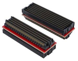
The connection sequence is straightforward. Mount the interposer onto the carrier’s FMC HPC site. Mount the FMC+ module onto the interposer’s HSPC connector. Observe normal ESD precautions; you are now handling a three-board stack with two connector transitions. Then power up and confirm enumeration: the module’s IPMI EEPROM should appear on the carrier’s I2C bus, and PRSNT_M2C_L should assert.
Four constraints deserve attention before you commit to this path.
Lane count. An FMC HPC carrier exposes ten transceiver pairs. An FMC+ module may offer up to 24, or 32 with HSPCe. You get the ten the carrier can reach; every remaining pair is left unconnected. Your JESD204B/C link configuration has to be scaled accordingly, typically fewer lanes per converter at a higher line rate, or fewer active converter channels.
Power headroom. FMC+ modules often draw more than older carriers were designed to supply, particularly RF front ends with their own PLLs and amplifiers. Check the module datasheet against the carrier’s mezzanine rail limits and the power-sequencing order before assuming it will run.
Clocking. Multi-gigabit links live or die on reference clock quality. With an interposer in the path, GBTCLK routing and jitter budget become more critical, not less. Allow bench time for clock-tree verification rather than assuming the links will lock.
Added insertion loss. Every connector transition costs margin. At 12 Gbps, this is manageable with this well-designed interposer, but plan on retuning pre-emphasis and equalisation, and budget time for eye measurements rather than assuming the link closes on first boot.
Mechanical fit still needs checking too. An interposer raises the whole stack, so keep-out zones, module height, and mounting-hole alignment all need verification; not every FMC+ module will fit, even with an adapter in place.
Sundance DSP has demonstrated this configuration in practice, using the adapter to interface two high-speed ADC channels from the FMCP-ADC3p0 FMC+ module to an SE120 carrier card with a standard FMC connector, maintaining signal integrity across the transition for reliable multi-gigabit capture.
Quick checklist: FMC+ module on FMC carrier
- Interposer fitted on standoffs
- Stack height and keep-outs verified
- Link design scaled to 10 lanes
- Carrier rails sized for the module
- GBTCLK jitter budget reviewed
- Transceiver EQ retuned and eyes measured
Choosing the right approach
If you are buying new, match generations and skip the adapter; an FMC+ carrier for an FMC+ module avoids the lane, power, and signal-integrity penalties entirely, and that matters most for high-lane-count or high-rate converters. If you already own the hardware, the decision is simple. An older mezzanine on a newer carrier needs little more than a VADJ and clearance check. A newer mezzanine on an older carrier needs an interposer and a realistic view of the lane count you will end up with. Either way, the mezzanine ecosystem is doing what it was designed to do: letting the expensive half of the system outlive the half you keep changing.