
The challenge with any sensor node deployed in the field is simple: get information from a remote location without drawing attention to the node itself. Transmit less, transmit shorter, and run cooler. Those three constraints shape the hardware you pick. The PolarBerry, a system-on-module from Sundance DSP, fits those constraints because the chip at its centre uses non-volatile FPGA technology, runs on roughly 12 watts at most, and draws its power over the same cable that carries its data.
This article looks at the PolarBerry and explains the chip it carries, then walks through a specific use case: placing the board as an Unattended Ground Sensor (UGS) to process local sensor data and send back only what matters, encrypted, over the network.
What is PolarBerry
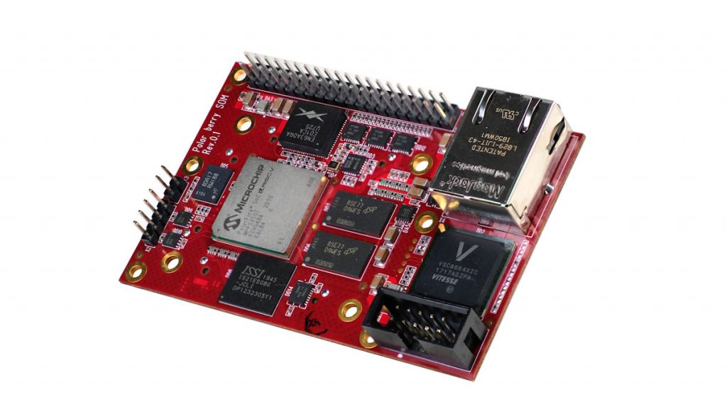
PolarBerry is a 55 mm by 85 mm module from Sundance DSP. It is built around the Microchip PolarFire SoC FPGA, specifically the MPFS250T-FCVG484 package. The module brings together the FPGA, 4 GB of DDR4 memory, 128 MB of SPI NOR flash for the boot image, 4 GB of eMMC storage, two CAN 2.0 physical layers, an RJ45 Gigabit Ethernet port, a 40-pin Raspberry Pi header, and high-speed Samtec connectors for carrier board attachment.
It is not a development kit in the hobbyist sense. Sundance positions it as a production and deployment-ready SoM, with the PoE revision now available as an ordering option. The PoE version means the module runs off a single Ethernet cable. No separate power supply, no barrel jack, no dedicated 5 V rail running alongside the data pair. One cable does both jobs.
That single-cable approach matters for field deployment. You run one pair of wires to each sensor node instead of a power supply plus a data link. The cable that feeds the node is the same one the node uses to send encrypted telemetry back to the network.
The chip underneath: PolarFire SoC
The PolarFire SoC was Microchip’s first RISC-V SoC FPGA to reach mass production. It sits on a non-volatile FPGA platform. The flip-flops in the fabric retain their values without continuous power. The result: the board boots instantly. SRAM FPGA requires you to load a bitstream from SPI flash every time the board powers on. The PolarFire SoC powers up and goes to work.
The processing cluster is a set of five RISC-V cores that all share a coherent 2 MB L2 memory subsystem:
- One E51 monitor core, 64-bit RV64IMAC, running at 625 MHz. This core handles boot, system monitoring, and always-on tasks that must be up before the application cores start.
- Four U54 application cores, 64-bit RV64GC, each at 625 MHz. These run Linux, an RTOS, or bare-metal code. They support virtual memory and a single- and double-precision FPU, and can be pinned to deterministic mode for real-time workloads.
The FPGA fabric provides 254,000 logic elements (4-input LUT with DFF), 784 math blocks (each 18×18 MACC), and 4 high-speed SerDes lanes running from 250 Mbps up to 12.5 Gbps per the MPFS250T PolarFire SoC specification (Sundance’s PolarBerry marketing lists 12.7 Gbps). There is 128 KB of on-chip non-volatile memory for user code that must be reachable immediately at power-up. The integrated DDR controller supports DDR3, DDR4, LPDDR3, and LPDDR4 with SECDED (single-error correct, double-error detect) enabled at all times.
The RISC-V cores use a simple 5-stage, single-issue, in-order pipeline. Microchip’s datasheet notes that this design does not suffer from Meltdown or Spectre vulnerabilities, which are class problems in out-of-order superscalar implementations. For a sensor node handling potentially adversarial input, that is a meaningful property.
Security features baked into the chip include:
- DPA-resistant Athena Terafire crypto coprocessor (available on “S”-suffixed devices), for AES, SHA, and other cryptographic primitives in hardware.
- Secure boot chain: the system controller loads the Microchip secure boot loader onto the E51 monitor core’s tightly integrated memory (DTIM) and releases reset; the loader then runs a signature check (ECDSA on the Secure Boot Image Certificate) followed by a hash on the 128 KB eNVM, and only if both pass is the eNVM code executed. A failure raises a BOOT_FAIL tamper flag in the fabric.
- Anti-tamper and anti-cloning detection.
- Physical Memory Protection (PMP) on every core, with 16 regions of minimum 4-byte granularity.
- Resistance to single-event upsets in the fabric configuration cells, a key advantage over SRAM FPGAs whose configuration must be reseeded after a bit-flip.
- SECDED on all processor memories and fabric LSRAMs.
These are not add-ons. They are part of the silicon.
Power: where the numbers actually go
Microchip’s public claims put the PolarFire SoC at up to 50% lower power than equivalent SRAM SoC FPGAs, with per-core figures of 3.125 CoreMarks per MHz and 1.714 DMIPS per MHz quoted in its product overview. The PolarBerry module draws 16 W at most, with the SoC itself capped at 12 W. That includes memory, transceivers, and all onboard peripherals.
No fan is needed for a 12 W SoC at 55 x 85 mm. Convection through a metal enclosure or a small heat spreader handles it. Sundance’s launch materials note that eliminating a fan and a dedicated power supply reduces the bill of materials and removes the two sources of audible noise and thermal output that are easiest to detect in a field deployment.
The non-volatile fabric means there is no configuration phase at boot. An SRAM FPGA can sit in a “loading bitstream and calibrating” state for many milliseconds, drawing current the whole time. The non-volatile fabric skips that window entirely. The board is in its steady-state operating mode from the instant it is powered on, and the steady-state current is lower than the SRAM equivalent.
PoE: one cable does everything
The newer revision of PolarBerry includes Power over Ethernet as an ordering option. All PoE boards are pin-compatible with the standard carrier-powered version. You can run a carrier-board-powered node and swap in a PoE-powered one in the same enclosure.
With PoE, the Ethernet cable delivers both data and power to the node. In a UGS deployment, this means:
- One physical cable per node, instead of a power supply plus a data link.
- No dedicated power distribution infrastructure at the node (no AC/DC brick, no isolated DC-DC converter chain, no thermal mass from a transformer).
- The same cable is the data egress point for encrypted telemetry.
- If the node is connected to a powered Ethernet switch at the base station, the node can be powered on when the switch is energised and powered down when the switch drops, with zero separate battery or generator at the remote end.
The board’s on-board power regulator handles the PoE input and supplies the 5 V and 3.3 V rails the SoC and peripherals need. The 16 W module draw needs a PoE+ switch: 802.3at provides up to 30 W at the powered switch and about 25.5 W at the powered device, which covers it. Standard 802.3af, at roughly 13 W at the powered device, would be too little for the 16 W module, so 802.3af alone cannot power the node.
Unattended Ground Sensors: the application
A UGS is a network of sensor nodes placed in a fixed area to monitor for activity: motion, acoustic signature, RF emissions, vibration, thermal anomalies, or a combination. The classical use case is perimeter defence. You want to detect a person, vehicle, or aircraft entering a monitored zone, identify the type and heading, and log or transmit that information. You do not want to stream raw sensor data to a central server for the full duration of the deployment.
The problem with a naive approach: an acoustic sensor produces thousands of samples per second. A vibration sensor produces thousands of amplitude readings per second. If you stream all of that over a radio link, two things happen. You burn bandwidth, and you emit RF on the air the entire time. Both of those are detectable. A high-throughput, continuous RF transmission is a signature. An adversary can direction-find a continuously transmitting node and find it.
The approach the PolarBerry supports is different. You process at the node. You decide locally what an event is. You transmit only the compressed, classified result, and only during a short transmission window. The node is silent for most of the time it is running.
Here is how the hardware maps to that workflow.
1. Ingest sensor data through FPGA fabric
The FPGA fabric ingests raw sensor data through its I/O banks. The 254k logic elements are more than enough to build decimation filters, band-pass selectors, envelope detectors, or FFT front-ends for the sensor channels you need. Because the fabric is non-volatile and the SoC can run the processing pipeline from the moment it boots, there is no boot latency window where the sensor link is running, but the processing chain is not yet configured.
The CAN 2.0 interfaces, available at two physical layers on the PolarBerry, give you a wired link to field sensor units that speak CAN or that sit behind a CAN adapter. The Raspberry Pi header provides 20 configurable GPIOs that can be assigned to SPI, UART, or other MSS interfaces as your sensor I/O requires.
2. Run detection algorithms on the RISC-V cores
Once the FPGA has cleaned and feature-extracted the sensor signal, the U54 cores run the classification logic. Depending on the sensor, this could be:
- Acoustic: match spectral features against a library of vehicle or human gait signatures.
- Vibration: template-match a ground signature pattern to discriminate footfall, wheeled vehicle, tracked vehicle, or wind.
- Multi-sensor fusion: cross-reference timestamps, bearings, and magnitudes across two or more sensor channels.
The four U54 cores run at 625 MHz with a coherent shared 2 MB L2 memory. The L2 can be partitioned as a cache for the general Linux workload, as loosely integrated memory (LIM) for the real-time pipeline, or as scratchpad for deterministic access. That partitioning is done at design time; the cores do not contend for it at runtime.
Deterministic mode lets you pin sensor processing to specific cores and guarantee worst-case interrupt latency. You do not have to schedule a sensor thread against a Linux network management thread and hope the scheduler favours the sensor path. The real-time core handles the sensor loop; the other cores handle the OS, networking, and key management.
3. Encrypt the result in hardware
Once a classification result is produced (a type, a heading, a confidence level, a timestamp), the AES or SHA path encrypts the packet. When the silicon is an “S” data-security variant, that encryption runs in the DPA-resistant hardware crypto coprocessor; otherwise it is handled in software on the RISC-V cores. This is the data that leaves the node. It is small. A few hundred bytes. The node transmits it during a short window, perhaps every 10 or 30 seconds, and then returns to idle.
4. Boot in seconds, not minutes
The non-volatile fabric means the PolarBerry is processing sensor data within milliseconds of the cable being energised. There is no 100 ms, nor 1 second, nor several seconds “I am loading my firmware” window where sensor data is being collected and not processed, or where the board is at peak current during its boot sequence. The node is in its operational state from the first edge of the power signal.
This matters if the node is turned off and on frequently (power management, maintenance, or field repositioning). Each cycle is instantaneous rather than a short period of noise on the sensor link while the boot sequence runs.
5. Deploy without a power supply
The PoE revision means you run one cable to each node. A PoE network switch at the base station powers the node and carries the telemetry back on the same pair. The node has no battery, no generator, no separate power supply, no transformer, no switching regulator in the deployment box. The thermal mass of the node is just the module, the enclosure, and the cable.
For a line of 10, 20, or 100 sensor nodes strung along a perimeter, this simplifies the cabling from two cable runs per node (power and data) to one.
What it is not
The PolarBerry is not a general-purpose IoT board in the same sense as a Raspberry Pi or an ESP32. It is a SoM for people who need the FPGA fabric, who need deterministic RISC-V cores, who need the security features in silicon rather than in software, and who are building a product. It expects a developer to work with the Libero SoC design suite, the SoftConsole RISC-V IDE, the Mi-V toolchain, and a Yocto or Buildroot Linux build or an RTOS port. The free 1-year Libero Silver license is available from Microchip.
SundanceDSP lists the PolarBerry at 0 to 70 C in its product prose but 0 to 100 C in its feature list on the same page, so the board-level range depends on the exact revision and grade. The MPFS250T die itself carries a wider envelope: the PolarFire SoC datasheet lists an extended commercial range of 0 to 100 C and an industrial range of -40 to 100 C (with AECQ-100 and Military grades available for higher ranges). For a fully unshielded outdoor deployment or an Arctic installation, either pair the node with a heated enclosure or move to the RT (radiation-tolerant) variant of the PolarFire SoC. Check the exact part number, board revision, and grade you are working with before committing hardware to an environment.
Summary
PolarBerry is a 55 x 85 mm SoM from Sundance DSP, powered down to 12 W at the SoC and 16 W at the module, carrying a 254k-logic-element non-volatile FPGA and five RISC-V cores. The PoE revision lets you run the whole node from a single Ethernet cable. For a UGS application, that means: instant boot with no bitstream load phase, FPGA hardware for sensor front-end processing, deterministic RISC-V cores for classification logic, hardware crypto for the encrypted telemetry packet, and a radio that is quiet most of the time because the data it carries is a few hundred bytes, not a multi-megabit raw stream.
The thermal cost of the node in the field is: 12 W of heat and nothing else. That is a very different detection target than the continuously transmitting, multi-watt battery-powered node that older field deployments required.
For a UGS program, the hardware question is how to get the sensor output to the operator with the lowest possible signature. PolarBerry answers that with a 12 W footprint, one cable, local processing, and encrypted data to send.