
Achieving Sub-Microsecond (Nanosecond-Class) Multi-Axis Motor Synchronization
1. Introduction: The Multi-Axis Synchronization Problem
Multi-axis robotic cells, high-speed CNC gantries, and packaging assembly lines share a common structural dependency. Every actuator’s position and velocity trajectories must be continuously phase-locked to every other actuator’s trajectory for the duration of the motion profile. A six-axis robotic arm performing a coordinated weld path, a five-axis CNC mill cutting a contoured surface, or a rotary packaging line synchronizing a flying-shear cutoff to a moving web all reduce to the same control problem: N independent servo loops must behave as if they were a single kinematic system.
The tolerance for divergence in that system is not generous. In CNC contouring, a phase lag of even a few microseconds between the X and Y axes at typical feed rates translates directly into contour error, visible as tool marks, dimensional drift, or, in extreme cases, tool breakage from unexpected cutting forces. In robotics, joint-to-joint timing skew accumulates through the kinematic chain and manifests as end-effector position error that scales with arm length and angular velocity. In packaging, a cutoff knife that is even one encoder count out of phase with web speed produces a scrap part.
Modern manufacturing throughput requirements compress these tolerances further every generation. A CNC spindle running at 24,000 RPM with a 0.5 mm feed per revolution requires axis updates on a timescale where a 50 μs synchronization error is already a measurable fraction of a single feed increment. Packaging lines have moved from web speeds of 200 m/min to 600+ m/min over the last decade, meaning the same absolute position error now represents three times the phase error per unit time. The net effect: the permissible timing window for closing multi-axis control loops has shrunk from the millisecond range to the low microsecond, and in some torque-loop-critical applications, tighter still, while the number of axes needing simultaneous service has grown.
This article examines why general-purpose host CPUs structurally cannot meet this requirement even with real-time operating system augmentation, and details a reference architecture, built around the Sundance DSP Solar Express 50 (SE50) Mini PCIe module, that closes these loops largely within FPGA fabric, removing host scheduling jitter from the timing-critical path. It’s worth stating up front that the specific TDM/FOC pipeline described in Section 4 is a custom-IP implementation an integrator would design and load onto the SE50’s PolarFire fabric, not a fixed function the module ships with out of the box; the SE50 itself is a general-purpose Mini PCIe FPGA carrier, and the control architecture is what you build on top of it.
2. Why General-Purpose CPUs Fail at Microsecond Determinism
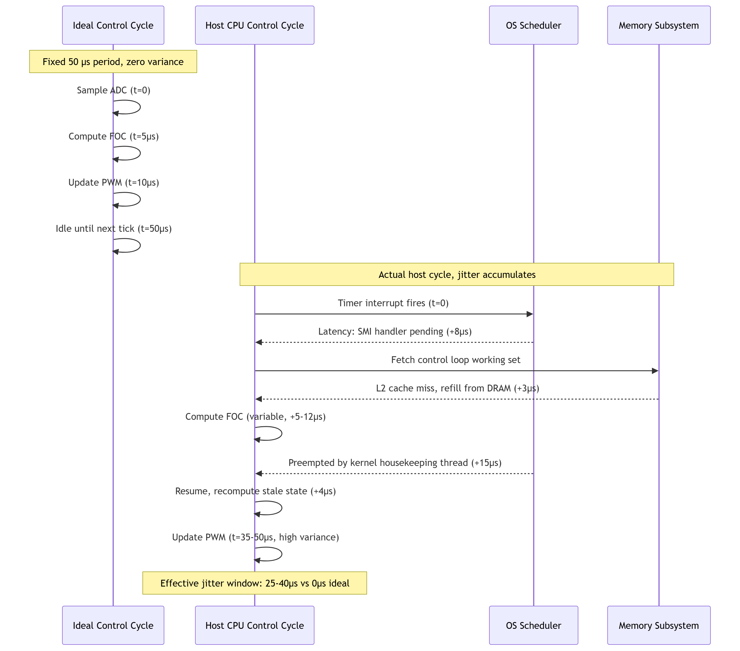
Industrial PCs (IPCs) running Xenomai, RT-Preempt-patched Linux, or similar real-time extensions can achieve impressively low average interrupt latencies, often in the 10–30 μs range for well-tuned systems. The problem for motor synchronization is not average latency; it is the variance of that latency, i.e., jitter.
Several architectural features of general-purpose CPUs are fundamentally incompatible with deterministic execution:
- Cache hierarchy behavior: A control loop’s working set may be resident in L1/L2 cache during one iteration and evicted by an unrelated kernel task, DMA-coherency flush, or another core’s memory traffic during the next. Cache misses on the critical path can add hundreds of nanoseconds to tens of microseconds unpredictably.
- Interrupt latency: Even with RTOS prioritization, hardware interrupts compete with SMI (System Management Interrupt) handlers, which on x86 platforms can be triggered by firmware-level events (thermal management, USB legacy emulation) entirely invisible to the OS scheduler and immune to RT priority.
- Context switch overhead: Every transition between the motor control thread and any other runnable task, including kernel housekeeping threads, costs fixed TLB/cache-warming overhead plus a variable amount of time depending on what displaced the working set.
- Bus and memory contention: Shared memory controllers mean a non-real-time process performing a large memcpy or GPU transfer can stall the memory bus long enough to blow a hard real-time deadline on an otherwise perfectly scheduled RT thread.
The compounding effect of these sources is that a control loop nominally executing every 50 μs might, over a large sample, show a jitter distribution with a long tail reaching several hundred microseconds. For a single-axis loop, this may be tolerable; for an N-axis synchronized system, each axis experiences an independent jitter distribution, and the worst-case phase divergence between any two axes is the sum of their individual worst-case deviations. This directly degrades PID and Field-Oriented Control (FOC) loop stability: the effective loop gain becomes time-varying, producing velocity ripple, cumulative phase error between axes, and, because ripple frequently lands in the audible range once integrated through the mechanical transmission, audible acoustic noise from the motor and gearbox.
Offloading the servo loop to dedicated hardware, as described below, addresses this specific failure mode, but trajectory generation, HMI, and diagnostic streaming still run on the host, so isolating those paths from the control loop (Section 5) remains part of the job.
3. Solution Overview: The Sundance DSP Solar Express 50 (SE50) Architecture
The SE50 (“Tiny Beast”) provides the hardware substrate for relocating a time-critical control loop out of host software and into FPGA fabric, connected to the host via a Mini PCIe edge connector. As shipped, it is a general-purpose FPGA carrier board rather than a preconfigured motor controller; the control logic described in Section 4 is custom IP that an integrator develops (typically in Microchip’s Libero SoC toolchain, available under a free license tier for this device class) and loads onto the fabric. Once the integrator has developed and loaded that custom IP, the host retains authority over trajectory planning, HMI, supervisory logic, and non-real-time diagnostics, while the FPGA owns the microsecond-to-nanosecond timing domain.

Core hardware specifications relevant to system integration:
- FPGA: Microchip PolarFire MPF300T, a flash-based mid-range fabric offering sufficient logic density for multiple parallel FOC/PID pipelines plus protocol decode logic for encoder feedback. The industrial-grade board variant (SE50-MPF300-1-I, discussed further in Section 6) targets extended temperature range deployments.
- Memory: 4 GB onboard DDR4, used as both working memory for FPGA soft-logic peripherals and a high-speed telemetry ring buffer.
- Host interface: PCIe Gen2 x1, configured as an Endpoint device, providing up to roughly 500 MB/s of theoretical per-direction bandwidth (sustained DMA throughput will be somewhat lower once protocol and transaction overhead are accounted for), ample for trajectory setpoint streaming and telemetry retrieval, while being physically and logically isolated from the time-critical loop.
- I/O: Samtec SS4 high-density connector, breaking out general-purpose I/O and high-speed transceiver lanes that can be used, with appropriate custom logic, for encoder inputs (BiSS-C, EnDat), PWM outputs, and auxiliary GPIO.
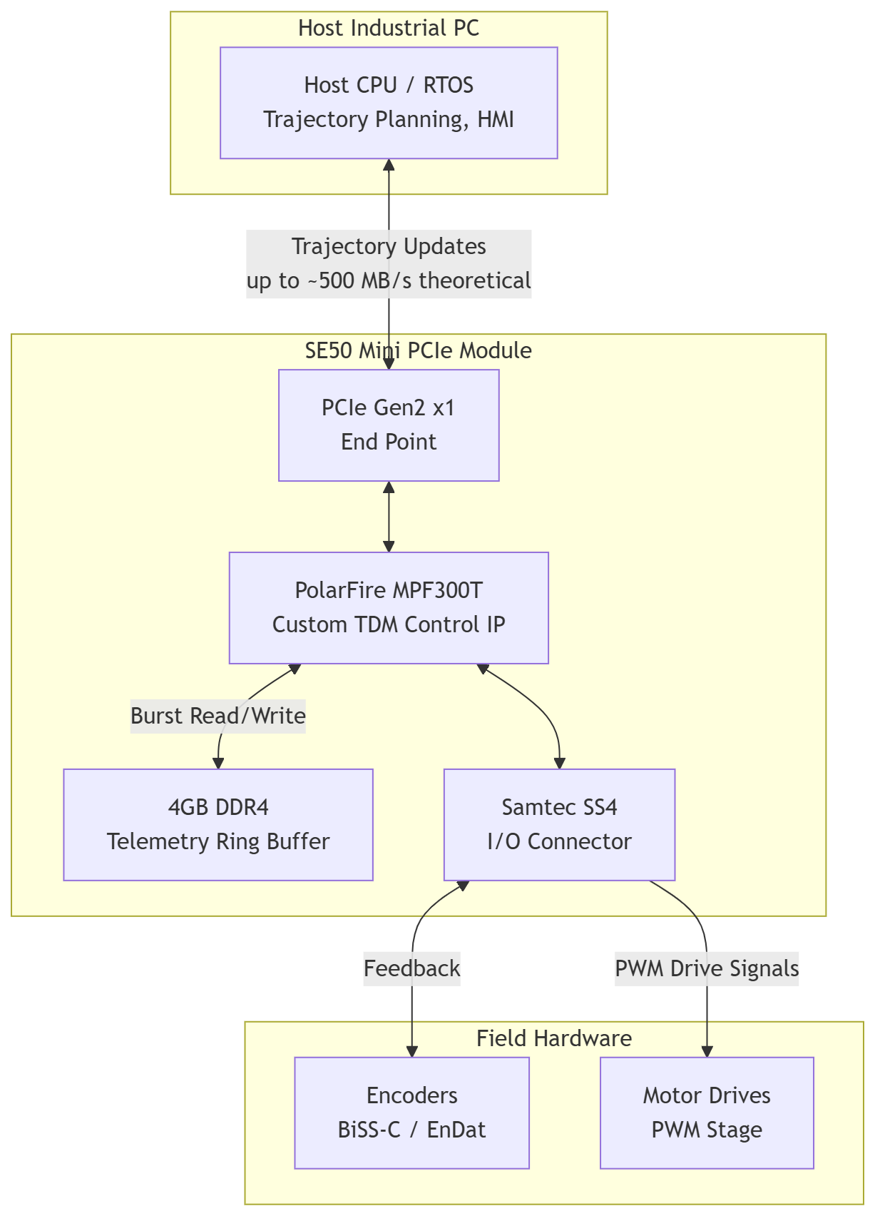
Because the PCIe link, in this architecture, carries only high-level, non-time-critical trajectory updates and telemetry, host-side OS jitter never enters the servo loop’s timing domain; the FPGA’s internal clock, not the host scheduler, governs every control decision inside the custom IP.
4. Deep Dive: Implementing Hardware-Level Time Division Multiplexing (TDM)
What follows is one reference approach to implementing a multi-axis FOC/PID controller within the PolarFire fabric, a design pattern an integrator would build using Libero SoC and the SE50’s fabric resources, not a feature present in the module as shipped. Within this reference design, each motor axis is assigned a fixed time slot within a master clock window; a shared pipeline processes encoder feedback, executes the control law, and emits updated PWM duty-cycle values for one axis per slot, cycling through all configured axes within a single, fixed-duration TDM frame.
The implementation proceeds through the following stages:
- Encoder ingest: BiSS-C or EnDat serial frames from each axis are deserialized by dedicated protocol-decode logic operating in parallel, so that position data for all axes is latched and available at the start of the TDM frame. Note that both protocols carry their own serialization latency, which sets a practical floor on how tightly the frame window can be closed; this is a system-level constraint independent of the FPGA fabric’s own speed.
- TDM scheduling: A master state machine advances through fixed time-slots, Axis 1, Axis 2, Axis 3, and so on, each slot given identical duration by the fabric’s synchronous clocking, with no possibility of preemption, cache eviction, or scheduling variance of the kind described in Section 2.
- Control law execution: Within each slot, the shared FOC/PID pipeline computes the Clarke/Park transforms, current-loop and velocity-loop error terms, and inverse transform back to PWM duty cycle, using the same fixed-latency arithmetic path for every axis.
- PWM emission: Updated duty-cycle values are latched to output registers synchronously at the frame boundary, so that all axes update simultaneously despite having been computed sequentially.
Actual achievable frame rates depend on fabric utilization, the complexity of the FOC/PID math, encoder protocol overhead, and clock frequency, typically targeting hundreds of kHz to low-MHz-class loop rates for multi-axis systems, rather than a fixed number that applies to every design.
Because every axis traverses an identical hardware path with identical propagation delay, phase alignment between axes is guaranteed by construction within the fabric, rather than by statistical convergence. It’s important to be precise about scope here: this guarantee applies to the timing domain inside the FPGA. End-to-end system synchronization also depends on cabling skew, drive/amplifier response time, and mechanical compliance, none of which the fabric can correct for, so “nanosecond-class” determinism describes the control computation and I/O timing, not a blanket claim about the physical motor shaft.

(The 1 μs frame with three 333 ns slots above is illustrative; actual slot count and duration are design parameters chosen for a given axis count, encoder protocol, and control-law complexity.)
The host’s role is reduced to writing updated trajectory targets (position, velocity, or torque setpoints) into a register/FIFO interface reachable over the PCIe Endpoint, an operation with generous timing tolerance, typically updated at 1–10 kHz, several orders of magnitude looser than the underlying hundreds-of-kHz-to-low-MHz-class TDM frame rate running inside the fabric.
5. Leveraging Onboard DDR4 and High-Speed I/O for Real-Time Diagnostics
The 4 GB DDR4 memory attached to the PolarFire fabric can serve a role distinct from general-purpose compute memory: configured as part of the custom IP, it functions as a high-bandwidth circular buffer that captures telemetry, phase currents, position tracking error, and torque estimates at the clock edge where each value is computed inside the TDM pipeline, with no host software involvement in the write path.
This matters because the alternative, streaming telemetry to the host in real time over a shared bus, reintroduces exactly the kind of bus contention and blocking behavior described in Section 2. By writing telemetry locally to the DDR4 ring buffer at wire speed and only later draining it to the host via DMA burst transfers over the PCIe link, the diagnostic data path is decoupled from the control data path. The host can request a burst read of, say, the last 10 ms of full-rate phase current data for post-mortem analysis of a fault event, without that read operation stalling the live TDM control cycle, provided the DMA arbitration logic in the custom IP is designed, as it should be, to give control-plane register writes priority over diagnostic-plane burst reads.
This effectively gives every axis an always-on, high-resolution “black box” recorder, which is of particular value for commissioning, tuning PID/FOC gains against captured real transients, and root-causing intermittent mechanical or electrical faults that would otherwise be invisible at host-side sampling rates.
6. Industrial Hardening: Why the PolarFire Architecture Fits the Factory Floor
Beyond raw timing determinism, the PolarFire fabric’s flash-based architecture offers properties that matter specifically for industrial deployment, rather than lab or bench conditions.
Instant-on recovery. Flash-based configuration cells hold the FPGA’s bitstream persistently and locally, meaning the device is fully configured and running control logic within milliseconds of power application; there is no external configuration PROM load sequence, and no dependency on an operating system completing a boot sequence before motion control resumes. In a factory context where a line experiences a brief power interruption, this is the difference between resuming production in single-digit milliseconds versus the tens of seconds required for an IPC to reboot an OS and reinitialize an SRAM-based FPGA via external bitstream load.
SEU immunity. Flash memory cells are inherently resistant to Single-Event Upsets caused by electrical transients, EMI from adjacent VFDs and contactors, or ionizing radiation, conditions common on a factory floor with large motor drives and switching power electronics nearby. Unlike SRAM-based FPGAs, where a bit flip in configuration memory can silently corrupt control logic until the next full reconfiguration, PolarFire’s flash configuration cells do not require continuous refresh and are not susceptible to the same upset mechanism.
Thermal and power envelope. The industrial-grade SE50-MPF300-1-I variant is rated across an extended -40°C to +100°C range, combined with the low static power draw characteristic of flash-based fabric compared to SRAM-based alternatives of similar logic density. This combination makes fanless, sealed IP67 enclosures mounted at the machine a realistic option for this variant, though whether a given design can actually run fanless still depends on the total power dissipated by the specific custom IP loaded, the enclosure’s thermal path, and ambient conditions at the installation; it isn’t automatic for every design loaded onto the fabric.
7. Conclusion: The Paradigm Shift in Motion Control Design
The underlying trade-off that has historically constrained motion control architecture, software flexibility on general-purpose CPUs versus hardware determinism on dedicated silicon, largely dissolves once the control loop is relocated to FPGA fabric and the host is relegated to trajectory planning and supervisory tasks. The SE50’s Mini PCIe form factor makes this relocation an incremental hardware and firmware/IP addition rather than a wholesale controller redesign: existing IPC infrastructure, HMI software, and PLC integration remain in place, while the microsecond-to-nanosecond timing domain is handed off to custom TDM control IP built for the PolarFire fabric.
The caveat worth carrying forward is that this determinism is earned, not automatic: it requires custom IP development, careful DMA/buffer design to keep diagnostics from perturbing control, and realistic expectations about where fabric-level guarantees end and system-level mechanics begin. With that understood, the SE50 gives architects designing the next generation of high-throughput CNC, robotic, and packaging systems a practical, incremental path toward tighter multi-axis synchronization, one that extends the useful life of existing IPC infrastructure rather than requiring it to be replaced outright.