
Introduction
Medical imaging equipment lives close to radiation. CT scanners, angiography suites, C-arms, linear accelerators, and PET/SPECT scanners all place sensitive electronics near an active radiation source. Sometimes the electronics sit just centimeters away. Over years of use, this exposure adds up. It can quietly damage boards that were never built to survive it.
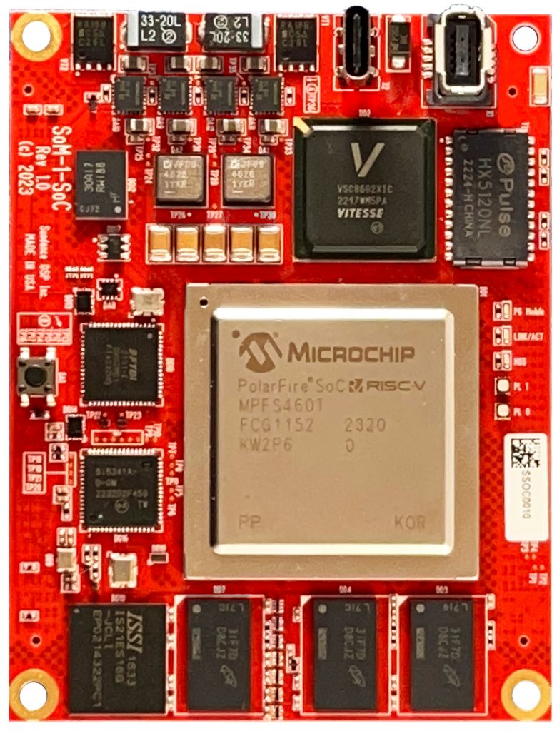
This is exactly the challenge the SOM1-SOC was built to handle. Sundance DSP designed this System-on-Module around the Microchip PolarFire SoC FPGA. Its flash-based, non-volatile fabric gives it real resistance to one of the most disruptive radiation effects in electronics: the single-event upset, or SEU. This article explains where radiation hides inside imaging systems, how it damages boards, and why PolarFire’s architecture helps. It also explains, honestly, what this architecture does not guarantee on its own.
Commercial Chip, Not a Space-Grade Chip
Let’s clear up one point right away. The SOM1-SOC uses the commercial-grade PolarFire SoC device (the MPFS460T or MPFS250T). It does not use Microchip’s separately qualified RT PolarFire SoC, the part built specifically for spacecraft.
Both chips share the same non-volatile, flash-based configuration technology. Both benefit from the same resistance to configuration-level SEUs. But the RT version goes through extra screening. Microchip tests it against heavy ions, protons, and neutrons. It carries guaranteed radiation-dose ratings and, in some cases, space-grade packaging.
So think of the SOM1-SOC this way: it inherits PolarFire’s architectural radiation advantage. It does not inherit the RT line’s certified radiation qualification. That distinction matters, and we’ll return to it.
Where Radiation Exists in a Medical Imaging System
People often assume radiation stays inside the beam that hits the patient. It doesn’t. Several distinct radiation zones exist around imaging equipment.
The primary beam and detector array. In CT, mammography, and general X-ray systems, the beam passes through the patient and strikes a detector. The electronics that process this detector data sit directly in the scatter field. In CT scanners, these boards often rotate around the patient at close range.
Scatter radiation inside the housing. Even boards outside the main beam absorb scattered photons. These bounce off the patient table and shielding. Over thousands of scans a year, this adds up to real cumulative dose.
LINAC treatment rooms. Radiotherapy machines use much higher energy beams than diagnostic imaging. Electronic portal imaging devices and dosimetry boards sit close to this beam. The beam can also generate neutrons inside the accelerator head. Neutrons are especially harsh on silicon.
Nuclear medicine scanners. In PET and SPECT imaging, the patient becomes the radiation source. Detector rings and readout electronics surround the patient closely and absorb radiation throughout the entire scan.
Interventional imaging suites. Cardiac catheterization labs and hybrid operating rooms expose control electronics to years of repeated, low-dose exposure. Long fluoroscopy runs add occasional spikes on top of that steady background.
In every one of these zones, boards face two threats at once: a slow buildup of dose, and sudden, random particle strikes. Both threats damage electronics, but in very different ways.
How Radiation Damages Electronic Boards
Radiation attacks silicon through a few distinct physical mechanisms. Understanding them explains why FPGA architecture matters so much.
Total Ionizing Dose (TID)
As radiation passes through a chip, it knocks loose electrons inside the transistor’s oxide layer. Some of these charges get trapped. Over time, trapped charge shifts the transistor’s switching threshold. Leakage current rises. Performance drifts. Eventually, the chip fails outright.
TID builds slowly. A board might work perfectly on day one. Then, after months or years inside a CT gantry or LINAC vault, it starts throwing errors. This is aging damage, not a single dramatic event.
Single Event Effects (SEE)
Unlike TID, single event effects happen in an instant. One high-energy particle; a neutron, proton, or heavy ion; strikes a sensitive spot in the silicon. That single strike can disturb the circuit immediately.
Several distinct failure types fall under this category:
- Single Event Upset (SEU). A particle flips a stored bit from 0 to 1, or back again. The transistor itself isn’t damaged. But the stored value changes. In a traditional SRAM-based FPGA, millions of these bits define the chip’s entire logic function. Flip one bit, and the chip’s wiring can silently change. A safety interlock might disable itself. A signal might route to the wrong place. And nothing alerts anyone until that broken function gets used.
- Single Event Latch-up (SEL). This one is worse. A particle strike triggers a short circuit between power rails inside the chip. Current surges. Heat builds fast. Left unchecked, SEL destroys the chip permanently — sometimes mid-scan, mid-treatment.
- Single Event Transient (SET) and Functional Interrupt (SEFI). These cause brief voltage glitches or force unexpected resets. Either one can send bad data downstream.
Why This Matters for Imaging Electronics
Picture an SEU that flips a bit controlling gantry rotation timing, or one that corrupts a dose-rate calculation. The system keeps running. It just runs wrong. That’s often more dangerous than a crash, because a crash at least gets noticed.
Why SRAM-Based FPGAs Struggle Here
Most high-performance FPGAs store their configuration in SRAM cells. SRAM works fast. It’s dense. But it’s also volatile; it holds its state in a powered circuit, and that circuit can flip when a particle passes through.
To manage this weakness, designers using SRAM FPGAs in radiation-heavy settings typically add:
- Constant configuration “scrubbing” (rewriting the bitstream on a loop to catch bit flips)
- Triple Modular Redundancy (TMR), which triples critical circuits and votes on the correct answer
- Extra shielding, which adds weight, cost, and complexity
- More complex fault-detection software
None of this removes the underlying weakness. It only manages it, at the cost of board space, power, and design time.
Why the SOM1-SOC Is Different
The SOM1-SOC’s PolarFire SoC uses a fundamentally different architecture. Instead of SRAM, it stores its configuration in non-volatile SONOS cells, flash-like memory that holds charge in a nitride layer rather than in a powered circuit. This single design choice changes the risk picture in several ways.
Configuration Bits Resist Upset
Because the configuration lives in trapped charge, not a powered latch, a passing particle has no simple way to flip it. This is the same SONOS cell technology used in Microchip’s radiation-tolerant RT PolarFire family, built for spacecraft and high-altitude avionics. Flash-based FPGA families have long been associated with high-reliability medical and industrial systems, and older families like RTG4 have specifically served nuclear plant control. The commercial PolarFire SoC shares this underlying cell technology, so it earns a real, structural advantage over comparable SRAM chips, without needing constant bitstream scrubbing.
But let’s be precise about what this covers. Configuration immunity protects the definition of the logic; the wiring and routing stay fixed. It does not automatically protect everything else on the chip. User flip-flops, combinational logic, hard IP blocks like the PCIe controller and transceivers, and the RISC-V processor subsystem can still experience transients or upsets during normal operation. That’s true for any advanced chip. So for the most safety-critical control paths, dose interlocks, motion limits, and emergency shutdowns, designers should still add TMR, watchdog timers, and independent hardware interlocks. The SOM1-SOC removes one major, historically dangerous failure mode. It doesn’t replace careful system design.
No Reconfiguration After an Upset
SRAM-based FPGAs that suffer a serious upset often need a full reconfiguration from external flash. That process can take the system offline mid-procedure. PolarFire SoC skips this risk entirely. Its configuration is non-volatile by nature, so the device stays “live” from the moment it powers on.
Memory Protection Beyond Configuration
Radiation can still disturb working memory, even on a flash-configured chip. That’s expected, and it’s why PolarFire SoC’s large SRAM (LSRAM) blocks include built-in error-correcting code. This ECC catches and fixes single-bit errors automatically, and detects double-bit errors. It’s a strong second layer of protection for image data flowing through the pipeline. Smaller micro-SRAM blocks don’t get this protection by default. Microchip offers an IP core to add it, and designers handling critical data there should use it.
A Genuinely Capable Processor, Not Just a Curiosity
None of this matters if the chip can’t do the job. The SOM1-SOC pairs PolarFire’s FPGA fabric, up to 461K logic elements, 20 transceivers running up to 12.7 Gbps, and two hard PCIe blocks, with a 64-bit, Linux-capable RISC-V processor. That combination handles real-time detector acquisition, image pre-processing, and reconstruction, all inside an 85x65mm module. It carries 4GB of DDR4 for the processor subsystem plus 8GB more for the FPGA fabric, 12GB total, along with 16GB of eMMC storage.
A Security Bonus
The same non-volatile technology protects PolarFire’s JTAG security fuses. A stray radiation event can’t accidentally unlock debug access to critical firmware. That matters for any networked medical device facing cybersecurity review.
Lower Power, Less Thermal Stress
Rotating CT gantries and compact C-arm heads don’t have much room to shed heat. PolarFire’s flash fabric runs at lower power than comparable SRAM FPGAs. Lower power means less heat stress on nearby components, components already fighting TID buildup from years of exposure.
Putting It Together: A Real Advantage, Honestly Framed
The stakes here are not abstract. A corrupted bit in a LINAC’s dose-rate logic could mean incorrect radiation delivery to a patient. A flipped bit in a gantry controller could mean a corrupted scan. Because SRAM-based SEUs don’t crash a system, they just make it run wrong, they rank among the most dangerous failure modes in radiation-heavy medical electronics.
The SOM1-SOC’s PolarFire architecture removes one of the most common and historically difficult versions of this problem: configuration-bit corruption. It does this at the hardware level, not through software patches layered on top. Add ECC-protected memory, strong I/O for detector interfacing, a capable RISC-V processor, and a low-power, compact form factor, and you get a genuinely strong foundation for radiation-adjacent medical design.
Still, keep this in perspective. The SOM1-SOC uses commercial silicon, not RT-qualified silicon, so it doesn’t carry the big price tag of RT qualified silicon. Seen that way, the SOM1-SOC isn’t a safety feature by itself. It’s a strong, well-founded reliability advantage, one that removes a historically dangerous class of silent failure and gives engineers a far more forgiving starting point for building a fully qualified, safety-critical imaging system.