
If you have worked with the Microchip PolarFire SoC architecture, specifically on customized hardware modules like the SundanceDSP SE301 / SOM1-SoC or PolarBerry, you quickly realize that traditional embedded boot mechanics do not apply here.
Unlike an ARM chip that searches for an MBR or a FAT32 partition to find a bootloader, the PolarFire SoC utilizes a rigid, hardware-level architecture. If your module is stuck boot-looping into a corrupt Linux kernel or an unconfigured U-Boot shell, you need to break the chain.
Because the SundanceDSP SOM1-SoC is designed as a production platform, it deliberately omits interfaces that would otherwise make field recovery convenient. It does not expose a physical USB-OTG port, and it boots from onboard eMMC rather than a removable SD card. Both choices are security-driven: a USB-OTG port would let anyone with physical access enumerate the board as a mass-storage device and read or rewrite the boot media directly, and a removable SD card can simply be pulled, cloned, or swapped by hand. Soldered eMMC and the absence of USB-OTG close off both of those low-effort attack paths, which is exactly why you can’t just mount the internal storage to a host computer to fix it. Instead, you must use low-level block destruction from within the boot chain itself.
Here is an architectural breakdown of how this board boots, followed by step-by-step instructions on how to strip out U-Boot and Linux to force the hardware to halt cleanly at the bare-metal Hart Software Services (HSS) prompt, and then how to bring it back to life with a full reflash.
The Anatomy of a PolarFire SoC Boot
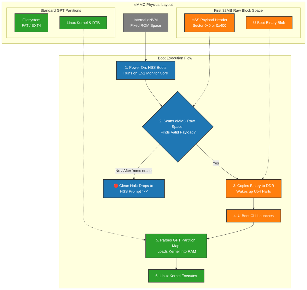
To understand how to stop the boot process, you need to understand how the three layers of the SOM1-SoC talk to each other:
Stage 1: HSS (Hart Software Services)
The HSS is Microchip’s initial boot code. It lives directly inside the chip’s internal non-volatile memory (eNVM). When you flip the power switch, HSS wakes up on the E51 monitor core, trains the external DDR memory, and scans the eMMC.
Crucially, HSS does not understand Linux filesystems. It looks for a raw, custom structural header called an HSS Payload (payload.bin) written directly to unpartitioned physical blocks on the storage chip.
2. Stage 2: U-Boot (The Bootloader)
On the SundanceDSP module, U-Boot is packaged inside that HSS payload. HSS validates the CRC checksum of the payload, copies the binary into your DDR RAM, and releases the main RISC-V application cores (the U54 cores). U-Boot then initializes and opens up its terminal interface.
3. Stage 3: Linux OS
Once U-Boot is alive, it takes over storage operations. It acts like a traditional bootloader, reading the eMMC partition tables (like GPT) to find your Linux kernel image, device tree blob, and root file system.
How to Completely Wipe U-Boot & Linux
If your goal is to drop directly into the HSS native prompt, bypassing U-Boot and Linux entirely, you have to break the payload formatting. Because U-Boot skips partition tables on this board, hitting block 0 with a standard tiny format tool will not stop it. You must run a heavy block erase.
Step 1: Drop to the U-Boot CLI
- The SE301 uses a single onboard USB bridge chip to provide both the JTAG debug link and the UART console. Connect the board’s micro-USB port to your PC with a standard USB cable; no separate JTAG pod or serial dongle is needed. This one connection is what you’ll use both to program the HSS later and to access the HSS/U-Boot terminal now.
- Open your terminal emulator (115200 baud) on the enumerated serial port and cycle the power to the board. (See “Finding Your Board’s UART Device” below if you’re not sure which
/dev/ttyUSB*node belongs to your board.) - The moment text hits the terminal, spam your spacebar or any key to stop the autoboot loop.
- You will land safely at a prompt similar to this:
SE301 REV0P0 VER1 SOM1SOC REV0p0 VER1 NO REV0p0 VER0: U-boot>
This exact string is just a sample; the prompt reflects how U-Boot was configured and built for your specific board revision, so yours may show a different board name, revision string, or version tag depending on how your U-Boot image was programmed.
Step 2: Target the Raw Disk
We need to ensure we are sending destructive instructions straight to the on-board eMMC user space. Initialize the storage subsystem by running:
mmc dev 0 0
This forces the hardware controller to point directly at eMMC Device 0, User Data Area 0.
Step 3: Obliterate the Raw Binary Sectors
Because the HSS configuration can flash the U-Boot payload deeper into the eMMC structure (often bypassing sector 0 entirely to hide it past partition lines), you need to fire a massive, sequential zero-fill across the storage.
Run this command:
mmc erase 0 0x10000
What is happening under the hood?
0: Sets the target memory boundary to start erasing at the absolute beginning of the physical flash memory.0x10000: Tells the controller to strip exactly 65,536 blocks. Since an eMMC block maps to 512 bytes, this cleans out the first 32 megabytes of continuous storage.
This sweep doesn’t care about partition types or file allocations; it flattens the custom HSS payload formatting, wipes the U-Boot binary workspace, and drops a zero-fill right through your early Linux partition boundary maps.
Step 4: Verify the Halt
On the SOM1-SoC and PolarBerry, neither the HSS nor U-Boot resets the board on its own; no software command reliably cycles the hardware back through the boot sequence. You need to perform a hard reset: either power-cycle the board (switch it off and back on) or press the physical reset button on the carrier board.
The Expected Result
Below is real HSS output captured after zero-filling the eMMC as described above (U-Boot deleted). As the module initializes, HSS trains DDR, selects the eMMC, then chokes as soon as it tries to read a payload header from the wiped storage:
DR training ... Passed
[4.932933] PolarFire(R) SoC Hart Software Services (HSS) - version 0.99.37-unknown
MPFS HAL version 2.2.104 / DDR Driver version 0.4.023 / BOARD=se301__som1soc__no
(c) Copyright 2017-2022 Microchip FPGA Embedded Systems Solutions.
incorporating OpenSBI - version 1.2
(c) Copyright 2019-2022 Western Digital Corporation.
[4.964346] Built with the following tools:
 - riscv64-buildroot-linux-gnu-gcc.br_real (Buildroot -g078199b-dirty) 11.4.0
 - GNU ld (GNU Binutils) 2.39
[4.979241] NOTICE: Running from L2 Scratchpad
[4.983919] Serial Number:
4570e65aef71dcce0a35dadff417ad9600000000000000000000000000000000000000000000000000000000000000000000
[4.996332] Segment Configuration:
        Cached: SEG0_0: offset 0x0080000000, physical DDR 0x00000000
        Cached: SEG0_1: offset 0x1000000000, physical DDR 0x30000000
    Non-cached: SEG1_2: offset 0x00c0000000, physical DDR 0xc0000000
Non-cached WCB: SEG1_4: offset 0x00d0000000, physical DDR 0xd0000000
[5.26408] L2 Cache Configuration:
    L2-Scratchpad:  4 ways (512 KiB)
         L2-Cache:  8 ways (1024 KiB)
           L2-LIM:  4 ways (512 KiB)
Clear Ethernet PHY RESET:
GPIO0_LO, PIN13: CLEARDONE
GPIO0_LO, PIN13: SETDONE
[5.48464] Attempting to select eMMC ... SD/eMMC internal demuxer is disabled!
Passed
Press a key to enter CLI, ESC to skip
Timeout in 2 seconds
..
[7.310810] CLI boot interrupt timeout
[7.314534] Initializing IPI Queues (6056 bytes @ a027750)...
[7.320454] Initializing PMPs
[7.323318] Initializing Boot Image ...
[7.327137] Trying to boot via MMC ...
[7.330861] Attempting to select eMMC ... SD/eMMC internal demuxer is disabled!
Passed
[7.587268] Preparing to copy from MMC to DDR ...
[7.592042] Attempting to read image header (1632 bytes) ...
[7.598170] magic is 00000000 vs expected b007c0de or c08b8355
[7.604186] HSS_Boot_VerifyMagic() failed
[7.608196] HSS_BootInit() returned 0
Init failed, press a key to prevent restart
Timeout in 5 seconds
Because the payload header now reads as all zeros instead of the expected magic value (b007c0de or c08b8355), HSS cannot verify a valid image and cleanly aborts the boot process, leaving you resting at the native Microchip HSS environment.
Your board is now successfully unlinked from U-Boot. From this bare-metal HSS environment, you can interact with the monitor core directly, ready to configure network boot routines via TFTP using the module’s Ethernet interface, or an HSS serial download session via Ymodem to upload and execute fresh bare-metal binaries.
Bringing it Back to Life: How to Reflash U-Boot and Linux
Once you have deliberately halted the board at the HSS prompt, it is time to look at how to reflash your firmware layers from scratch.
The recovery ecosystem for the SundanceDSP SE301 / SOM1-SoC relies on a layered, modular programming hierarchy. Each bootloader layer acts as the necessary staging tool to install the next component.
Understanding the Reflashing Hierarchy
The installation tools utilize three distinct transport mediums depending on which layer you are writing:
| Programming Step | Hardware Mechanism & Transport Interface |
|---|---|
| 1. HSS | Onboard JTAG-to-USB chip (no external JTAG pod required) |
| 2. U-Boot | UART interface exposed by the active HSS firmware |
| 3. Linux Kernel | Ethernet network interface (TFTP server managed by U-Boot) |
Because each layer acts as the server installer for the next, you must flash them in sequence or use an automated orchestration script.
Step 1: Verify Your Buildroot Outputs
Before attempting a reflash, you must ensure that your Linux build process completed successfully. Navigating your host directory tree:
- Go to your active Buildroot workspace:
<build_root>/output/images/ - Confirm that
payload.bin(which packages U-Boot) exists. - Confirm that the Linux target image file exists. It will be named:
se301_rev0p0_ver1__som1soc_rev0p0_ver1__no_rev0p0_ver0_.itb
Finding Your Board’s UART Device
Because the SE301’s onboard bridge chip handles both JTAG and UART over the same micro-USB connection, your Linux host will enumerate it as one or more /dev/ttyUSB* nodes when you plug it in. Which number it gets — ttyUSB0, ttyUSB1, etc. — depends on what else is already connected to your machine and the order devices were plugged in, so you shouldn’t assume it’s always the same one. Here’s how to pin down the right one before editing FLASH_CONFIG.CONF:
- Check what’s already there. Before connecting the board, list any existing serial devices so you have a baseline:
ls /dev/ttyUSB*(It’s fine if this comes back empty or with “No such file or directory.”)
- Plug in the board and check again. Connect the SE301’s micro-USB to your PC, then re-run:
ls /dev/ttyUSB*Whichever node is new compared to your baseline is the board’s serial interface.
- Confirm it with
dmesg. This shows the kernel’s own enumeration log, which is the most reliable way to match the device to your board:dmesg | tail -n 20Look for a line referencing a new USB-serial converter and the corresponding
ttyUSBXassignment — it will appear immediately after you plug the board in. - If multiple ttyUSB nodes appear at once, the bridge chip may expose more than one interface (for example, a JTAG channel alongside the UART channel). Only the one accepting a standard serial connection at 115200 baud and printing readable HSS/U-Boot text is the console port; open each candidate in your terminal emulator to confirm which one responds.
- For a stable, permanent reference (especially useful if you have more than one board or dev board attached at a time), query the device’s USB serial number and use it to write a udev rule instead of hardcoding a
ttyUSBnumber:udevadm info -a -n /dev/ttyUSBX | grep -i serialYou can then create a rule under
/etc/udev/rules.d/that maps that serial number to a fixed symlink (e.g./dev/se301-uart), so the device name never shifts between reboots or reconnections.
Once you’ve identified the correct node, set it in FLASH_CONFIG.CONF as shown below.
Step 2: Configure the Target Environment (FLASH_CONFIG.CONF)
SundanceDSP provides a central hardware map file inside the Board Support Package (BSP) to link your network infrastructure and build directories to the physical deployment scripts.
Navigate to the scripting workspace:
cd sdsp_bsp/board/microchip/SE301_som1soc_no/
Open FLASH_CONFIG.CONF in a text editor. Here is the file’s default content as shipped:
BUILDROOT_DIRECTORY="../../../../buildroot-2023.08.1"				#set here path the buildroot you are used for building
UART_DEVICE="/dev/ttyUSB1"							#set here SE301 with SOM1_SOM board UART device in linux
DEVICE_IP="192.168.90.72"							#set here IP ADDRESS used for SOM1_SOC board that you want to flash
PC_IP="192.168.1.106"								#set here IP ADDRESS of you PC
IMAGE_NAME="se301_rev0p0_ver1__som1soc_rev0p0_ver1__no_rev0p0_ver0_.itb"	#set here file name of the linux image (it shall be placed in the TFTP directory)
You’ll almost always need to edit at least two of these lines for your own setup:
UART_DEVICE: the default/dev/ttyUSB1is only a placeholder. Replace it with whatever you found using the “Finding Your Board’s UART Device” steps above.PC_IP: set this to your host PC’s real IP address on the network interface connected to the board’s Ethernet port (check withip addron Linux).DEVICE_IPis a temporary address assigned to the board itself during recovery and just needs to be a free address on that same subnet.BUILDROOT_DIRECTORY: the default is a relative path (../../../../buildroot-2023.08.1) assuming a standard BSP/Buildroot directory layout side by side. If your Buildroot workspace lives somewhere else, point this at its absolute path instead.
⚠️ CRITICAL WARNING: Before running any automation tools, close all active terminal emulators (like Minicom or Screen) binding to your target UART_DEVICE. Leaving a terminal window active will lock the serial device node, causing the flash injection scripts to fail silently or corrupt the stream.
Step 3: Executing the Reflash Sequence
SundanceDSP populates this folder with four core management shell scripts. You have two execution options depending on the current health state of your hardware module:
Option A: Automated Total Deployment (Virgin or Fully Wiped Module)
If you have just run the raw block erase procedure above, and the eMMC is entirely blank, run the global orchestration script:
./programm_all.sh
This utility handles the entire dependency chain linearly: it connects via JTAG to drop in the basic bootloader, pivots to UART to deploy U-Boot, and shifts to your networking adapters to flash the OS.
Option B: Component-Specific Reconstruction (Granular Recovery)
If the automated master script errors out due to connection timeouts, you should manually sequence the modular scripts one by one:
./Programm_hss.shTarget: Overwrites the core HSS bootloader inside the chip’s internal eNVM. Requirement: Requires only the USB-JTAG connection cable. You only need to run this if you are booting a completely fresh chip or have modified the primary HSS source code configuration../programm_uboot.shTarget: Writes the U-Boot framework payload image onto the raw block sectors of the eMMC drive. Requirement: Assumes the board already has active HSS running. It automatically intercepts the HSS interface via UART to upload the payload../programm_linux.shTarget: Pulls the kernel, device tree, and root filesystem from your host computer and writes them to the eMMC system partitions. Requirement: Requires a valid network path. U-Boot initializes the local interface using yourDEVICE_IPsettings and fetches the target file from the activetftpd-hpahost network folder pointing to yourPC_IP.
Setting Up TFTP to Program the Linux Image
The Linux kernel/rootfs stage (./programm_linux.sh) is delivered over Ethernet: U-Boot, running on the board, issues a TFTP request to your PC to pull down the .itb image and write it to eMMC. For this to work, your host needs a TFTP server running and pointed at the right directory before you launch the script.
1. Install a TFTP server on your host. On Debian/Ubuntu:
sudo apt install tftpd-hpa
2. Configure it. Edit /etc/default/tftpd-hpa:
TFTP_USERNAME="tftp"
TFTP_DIRECTORY="/srv/tftp"
TFTP_ADDRESS="0.0.0.0:69"
TFTP_OPTIONS="--secure"
TFTP_DIRECTORY is the folder U-Boot will pull files from; it’s where IMAGE_NAME (the .itb file) needs to live.
3. Create the directory and restart the service:
sudo mkdir -p /srv/tftp
sudo chown tftp:tftp /srv/tftp
sudo systemctl restart tftpd-hpa
sudo systemctl enable tftpd-hpa
4. Copy your built image into place:
cp <build_root>/output/images/se301_rev0p0_ver1__som1soc_rev0p0_ver1__no_rev0p0_ver0_.itb /srv/tftp/
This filename must match IMAGE_NAME in FLASH_CONFIG.CONF exactly.
5. Sanity-check the server from the same host before involving the board:
tftp 127.0.0.1 -c get se301_rev0p0_ver1__som1soc_rev0p0_ver1__no_rev0p0_ver0_.itb
If that pulls the file down without error, the server is serving correctly.
6. Check your network path to the board. PC_IP and DEVICE_IP in FLASH_CONFIG.CONF both need to sit on the same subnet, and whatever cable/switch connects your PC’s Ethernet port to the board’s Ethernet port needs to be live; most setups use a direct link or a small unmanaged switch between the two, since the board doesn’t have general LAN access during recovery. Also make sure your host firewall isn’t blocking UDP port 69 (TFTP’s port), which is a common silent failure point.
Once the server is confirmed working and reachable, ./programm_linux.sh (or ./programm_all.sh) drives U-Boot through the equivalent of setting its network environment (ipaddr to DEVICE_IP, serverip to PC_IP), issuing a tftpboot request for IMAGE_NAME, and writing the received image to the eMMC’s Linux partitions, all automated, so you shouldn’t need to type any of that manually at the U-Boot prompt.
Post-Installation Note: Setting Up Persistent Storage
Once the board boots cleanly into Linux, your active operating system partition will not consume the entire remaining space on the internal eMMC.
To claim the remaining physical capacity for custom applications and application data storage without risking structural corruption during future firmware updates, run the module’s embedded volume script:
make_emmc.sh
This formatting shell script isolates the unallocated flash blocks, overlays an independent ext4 filesystem structure, and modifies your mount tables. On subsequent boot-ups, the space is map-linked straight to /mnt/emmc.
Because it lives completely outside the payload blocks and partition spaces targeted by your flashing utilities, reflashing HSS, U-Boot, or Linux in the future will not impact or wipe any persistent customer data residing on this storage partition.
With HSS, U-Boot, and Linux all reflashed and the persistent storage partition mapped, the SOM1-SoC module is back to a fully operational, factory-equivalent state.